Your Universal Remote Control Center
RemoteCentral.com
Lighting & Home Control Forum - View Post
Previous section Next section Up level
Up level
The following page was printed from RemoteCentral.com:

Login:
Pass:


Topic:
X10 switch wiring help?!
This thread has 3 replies. Displaying all posts.
Post 1 made on Sunday September 5, 2004 at 19:32
stelman
Lurking Member
Joined:
Posts:
September 2004
2
I am trying to install an X10 light switch to replace a normal switch so I can control when one of my outdoor lights goes on (Smarthome 23883 - [Link: smarthome.com])

It will be installed into a quadruple gang box to replace one of the four light switches. All the rest are normal switches. (One is three-way)

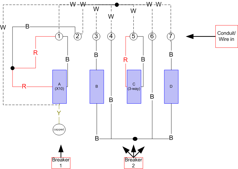
Please refer to the wiring diagram at the bottom of my post.

The switch I am replacing is the left-most one in the diagram, labelled "A". The other remaining switches are labelled "B", "C", and "D". "C" is a three-way switch.

Seven different sets of wires enter/leave the box, and are labelled "conduit" 1 through 7. Ground is not shown in the diagram, but all of the ground wires from conduits 1 through 7 are joined together, much in the same way as the white wires.

The switch I am replacing ("A") is on a different circuit breaker from the other three switches ("B", "C", "D"), which are all on the same breaker.

The old switch "A" that I removed was wired as follows:
a) "upper" wire connected to red wire coming in from conduit "1", and joined to black wire coming in from conduit "2"
b) "lower" wire connected to black wire coming in from conduit "1"

I wired the new switch the same way, attaching:
a) the red from the switch to the red from conduit "1" (still coupled to the black from conduit "2")
b) the black from the switch to the black from conduit "1"
c) the white from the switch to the splice of all the other white wires coming from conduit 1 through 7.
d) the ground from the switch to the splice of all the other ground wires coming from conduit 1 through 7.
e) the yellow wire is capped.

What did I do wrong? The LED on the X10 switch does not come on. The installation instructions say this would indicate that it's working (or at least has power).

On another note, if anyone has the time to help me figure out what all of the other wires are (which are hot, and which go to light fixtures), if you can tell from the diagram, that would be great too. I guessing that "1", "3", "5", and "7" go to light fixtures? Is "2" hot for breaker 1? What are "4" and "6"? The middle of a circuit that feeds switches "B", "C", and "D"?
Post 2 made on Sunday September 5, 2004 at 21:23
Larry Fine
Loyal Member
Joined:
Posts:
August 2001
5,002
Usually, when a cable with black and red is wired like this, the blacks are tied together, and the red is the switched wire. But, let's assume you're correct.

1. Swap the red and black from the switch. According to the way the black and red (cond. 1 & 2) are tied together, they are the feed-in and feed-out, and the single black (cond. 1) is the switched leg.

2. 1 OR 2 goes to a fixture, and 3 and 7 do. 5 goes to the companion 3-way, which in turn feeds the fixture (and it appears that your drawing is missing a line from the black dot at the bottom to the 3-way).

Yes, cond's 4 and 6 are the feed in and feed out for ckt. #2. You could say that this is "in the middle" of the circuit. The point is that one of them is the feed, and the other feeds an additional switch and/or receptacle box elsewhere.

Either the black from cond. 2 or the red from cond. 1 is the feed for ckt. #1, the other continues the circuit, as above for ckt. #2. Actually, there is one other possibility: the black from cond.1 is the feed, and the other two wires feed two different fixtures that operate together (but if this were the case, the X-10 should function, so never mind).

Let us know if this helps.
OP | Post 3 made on Sunday September 5, 2004 at 23:09
stelman
Lurking Member
Joined:
Posts:
September 2004
2
Thanks! That did it. (And just before dark!) I think maybe it makes sense, too. After reading your post, I remembered that this switch used to be a three-way before I moved here. The previous owner tied the other end together. Hence the red wire?

I've now got Black-switch to Black-#2 (with the red #1 still tied in), and Red-switch to Black-#1, and it all works. Does this seem correct?

Post 4 made on Monday September 6, 2004 at 01:11
Larry Fine
Loyal Member
Joined:
Posts:
August 2001
5,002
Yeppers!

Keep in mind that, if this used to be a 3-way, and the black and red were travelers, that the other end of the red wire is also hot, so make sure it's capped (or otherwise in use).


Jump to


Protected Feature Before you can reply to a message...
You must first register for a Remote Central user account - it's fast and free! Or, if you already have an account, please login now.

Please read the following: Unsolicited commercial advertisements are absolutely not permitted on this forum. Other private buy & sell messages should be posted to our Marketplace. For information on how to advertise your service or product click here. Remote Central reserves the right to remove or modify any post that is deemed inappropriate.

Hosting Services by ipHouse