On July 25, 2015 at 23:47, Ernie Gilman said...
While this is simpler it brings up some things I left out on purpose.
I think it's not leakage current, but minimum voltage drop across the transistor when it's on full. With NPN and PNP transistors, that's in the range of 0.6 volts, germanium 0.3 volts. But we don't use germanium for output devices because they can't pass as much current as the other technologies. I do't know what it is for other kinds of devices.
I must go look up threshold voltage, though that description doesn't include any "extra voltage drop...." wait a minute: that's probably the standard voltage drop across a junction.
Close. That voltage drop is only valid for BJT's. There are down drops. One across the Base Emitter junction, VBE, and one across the Collector Emitter junction, VCE. For a BJT to be in "amplification" or active mode, it requires a VBE of ~0.7V and a VCE>VCEsat. VCEsat is generally ~0.2V. For MOSFETS this is different. Most ICs mostly consist of FETS now a days. One of the few drawbacks of using MOSFET's instead of BJT's is power, thus BJTs still exist in almost all amplification circuit. One of the largest benefits of MOSFETs is that no current flows into their gate and also, the gate is pretty much a capacitor thus it has infinite input impedance. Like BJT's, FET's also have different operating modes. Additionally, they have a threshold voltage. This is actually a built in chemical potential that must be overcome for the device to turn "on".
There's another issue that makes this kind of amp look like it outputs less than rail to rail. If it could swing completely from rail to rail, that's its instantaneous voltage. If the signal is a sine wave, its RMS voltage is 0.707 times its peak voltage. So in this particular perfect world, an amp that outputs 10 volts peak to peak, with a plus and minus 10 volt power supply (20 volts rail to rail), outputs 7.07 volts RMS. I threw in the 20 volt number because it's true that rail to rail is twice the peak voltage of the RMS voltage, and I didn't want someone coming back to say "but wait, there's 20 volts there! How does it become 7.07 at full volume?"
The only way to actually get the supply voltage at the output of a transistor is to put it into cutoff mode. Ideally, this means that there is zero current flowing through the transistor, which is the path to ground, thus allowing for the supply voltage to appear at the output node. The problem is that due to leakage current, the current in cutoff mode will never be zero, causing a voltage drop and thus making the output voltage less than the supply. There are a lot of other factors that can cause this issue like frequency,etc. I am not sure if I understand your question, though?
I haven't investigated actual input circuits for years, but I doubt that most inputs are FET inputs. Back in plain old transistor days, some line inputs went directly to an input buffer, some went through switching, volume and tone without any amplification at all! In other words, things varied.
Yes, this is exactly true. Input stages are usually buffer stages and that is to ensure that input impedance is nearly infinity. Most buffers, or in other words source followers, are made of MOSFETs entirely.
Another high input impedance device is the op amp. The inverting input is a short to ground and the noninverting input is (ideally) an open circuit! Both of those facts dramatically change the details of how the line level signal is handled.
Op amps are high input impedance generally because of their buffered inputs (either source followers or emitter followers). The inverting input is definitely not a short to ground. It depends on the design. A bare op-amp without anything connected to it outside of the IC is a differential amplifier with almost infinite gain. Negative feedback allows you to set gain, lower output impedance, and raise the input impedance.
The output impedance of an amp is an impedance in series with the output, not in parallel. An amp with zero output impedance will not decrease in output voltage due to low impedance loads. Those are the kind of amps that blow up or weld when their active outputs are shorted with a signal coming out of them.
This is not true. First, if the output was a series resistance with the load, a load would never change the amount of current drawn because it is in series. Additionally, if you look at a transistor level circuit diagram of any basic differential amplifier (not even a full blown op amp) you will see that the output impedance always falls in parallel with the load resistance and that is why low impedance loads change the actual gain (by changing the circuit) and thus make for a lower output. Look at the picture below:
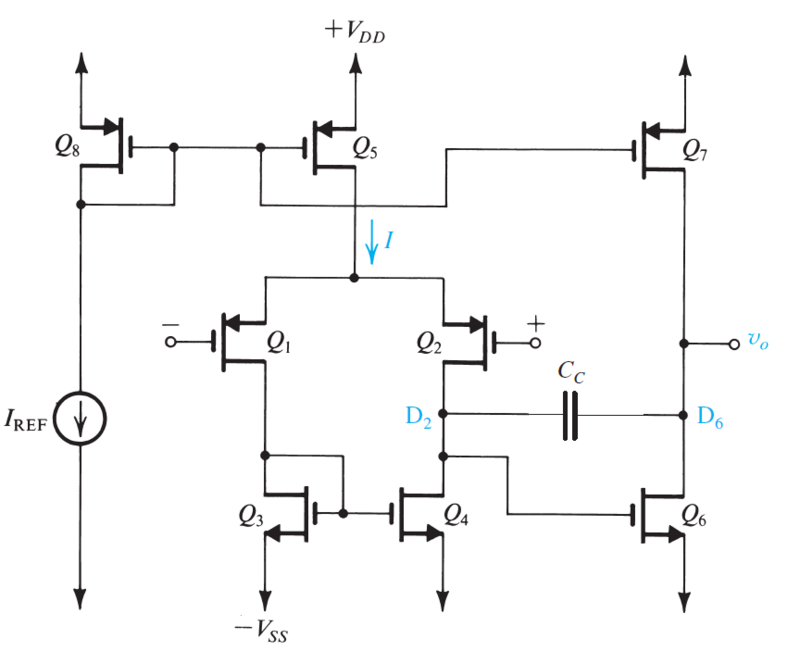
This is a very simple two stage op amp. If you look at the output node, you will see that the output impedance is the impedance seen at the drain of Q6 in parallel with the resistance seen at the drain of Q7. A load resistance will fall in parallel with the resistance seen at the drain of Q7 and thus it wall fall in parallel with the final output impedance.
Output impedance limits the amount of current that can be delivered, I agree. But that means it can't be in parallel with the load. An output impedance of zero ohms per that concept is a short circuit across the output. Look up buildout resistance for an example of adding resistance in series with an output in order to get a better result.
You are right, the value is never actually zero, but ideally, it should be. There are a couple of things I've learned in amplifier designs and that is that a perfect amp has the following:
1. infinite differential gain
2. zero common mode gain and thus infinite CMRR
3. infinite input impedance
4. zero output impedance
5. infinite bandwidth
6. zero input offset voltage
Yes.
crosen, maybe you can ask another question if all this has been so much as to obscure the thing you wanted to ask about!


